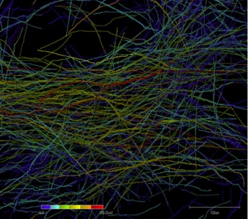
Fiber detail measurement
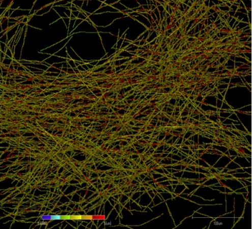
Fiber width measurement
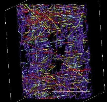
Detailed fiber angle measurement
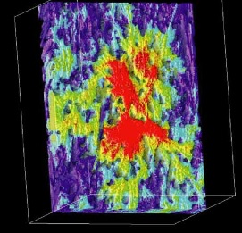
Detailed measurement of fiber dispersion
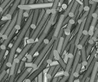
Mesh generation for finite element analysis
 Fiber detail measurement |
 Fiber width measurement |
 Detailed fiber angle measurement |
 Detailed measurement of fiber dispersion |
 Mesh generation for finite element analysis |
|
fiber measurementĀ@TRI/3D-FBR
Based on the É X-ray CT image of the 3D structure, this software is able to detect the fibers, glass fibers,3D measurement of local orientation, anisotropy, dispersibility, etc. of anisotropic structures. This software works as an option of TRI/3D-VOL.BON. The fiber detail measurement option (DT2) separates overlapping fibers and measures the length and orientation direction of each fiber. Results are output to an Excel readable tabular file for each fiber.
|